
How to connect three VFDs with one solar system?
Managing multiple motors with solar power can be a headache for project managers. If you design the system poorly, you will face constant power trips and wasted energy costs. I will share a proven architecture to run three VFDs smoothly from a single solar array.
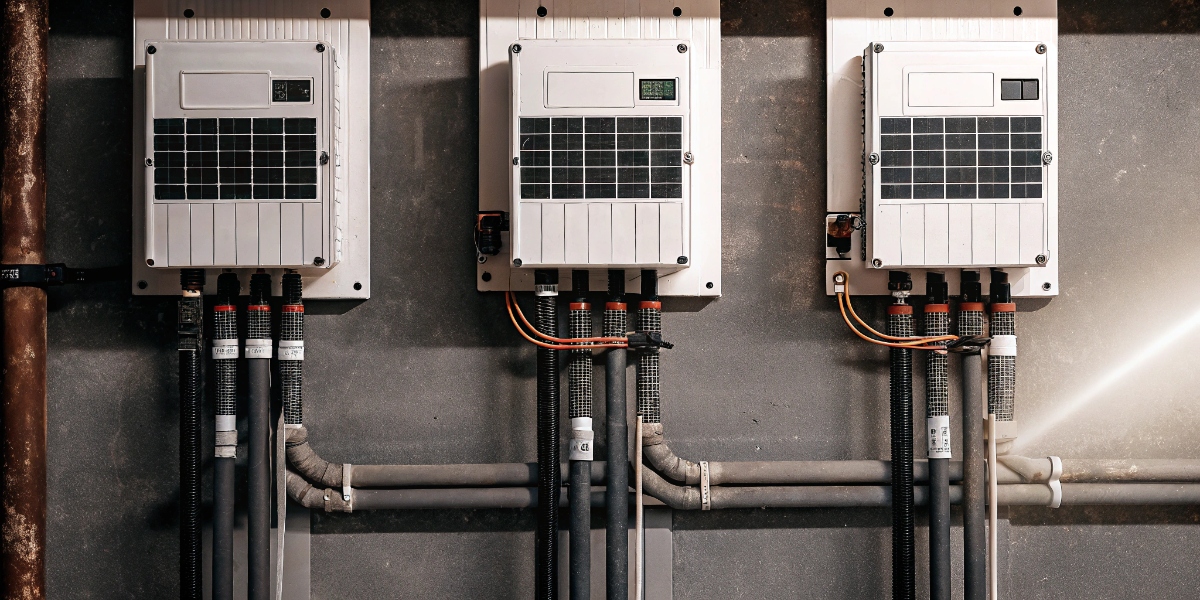
The most efficient method is to adopt a common DC-bus architecture1. You connect the Solar PV MPPT output2 directly to the DC links of the three VFDs through isolation and DC fusing. This avoids double conversion losses and allows the drives to share energy for higher efficiency.
Many engineers try to convert solar DC to AC first, and then feed the VFDs. This is a mistake. It increases the equipment you need to buy. It also lowers the total system efficiency. By using the method I described above, you save money and space. Let’s look at the specific components you need to make this work.
What is solar VFD?
You see this term on many product lists, but specifications can be confusing. If you buy the wrong type of drive, your solar system will not function correctly.
A solar VFD is a variable frequency drive specifically designed to accept DC input directly from photovoltaic panels. It features built-in Maximum Power Point Tracking3 (MPPT) algorithms. This technology adjusts the motor speed based on real-time sunlight intensity to keep the system running without stalling.

When I founded YOGU, I learned that standard industrial drives are different from solar drives. You cannot just swap them. To connect three VFDs to one system, you need drives that can handle power fluctuations. This is where the technical specifications matter for a purchasing manager.
You need to specify VFDs that have active front ends4 or specific input reactors. Solar power quality changes fast. When a cloud passes over, the voltage drops. If your VFD is cheap, it creates harmonics. Harmonics are dirty electricity that causes heat and damage.
I recommend looking for these features in your supplier list:
- IEEE 1547 Compliance: This ensures the inverter settings play nicely with the grid or your local generator.
- Active Front Ends: These stabilize the shared bus voltage.
- Harmonic Filters5: These reduce Total Harmonic Distortion6 (THD).
Here is a breakdown of why these features matter for your equipment life:
| Feature | Function | Benefit for Buyer |
|---|---|---|
| MPPT Algorithm | Tracks optimal solar power | Prevents nuisance tripping |
| Input Reactor | Smooths current spikes | Extends capacitor life |
| Low-Voltage Ride-Through | Keeps running during dips | Maintains production uptime |
By choosing VFDs with these specs, you safeguard the equipment. You reduce the risk of returns and failures at the project site. This makes your procurement process much more successful in the long run.
How do you convert single phase to three-phase with VFD?
In many remote projects, you might only have single-phase grid power as a backup, or just the DC solar feed. You still need to run heavy three-phase industrial pumps.
You can input single-phase AC or the DC solar power directly into the VFD terminals. The VFD creates an internal DC bus voltage. Then, the output IGBTs switch this DC voltage to create a balanced three-phase AC output for your motors.
This conversion process is the key to our common DC-bus architecture. When we connect three VFDs to one solar system, we do not treat them as three separate machines. We treat them as one big system.
In a traditional setup, you might have:
- Solar Panels -> Inverter (DC to AC)
- AC Distribution Panel
- VFD (AC to DC to AC) -> Motor
This is wasteful. You lose energy every time you convert the power.
In my recommended approach (Common DC-Bus), the flow is simpler:
- Solar Panels -> DC/DC MPPT
- Common DC Bus -> Three VFDs (DC to AC) -> Motors
This architecture avoids double conversion losses. It also enables energy sharing. Imagine one motor is braking (slowing down). It acts like a generator. It sends power back to the DC bus. The other two motors can use this free energy immediately. This increases your overall system efficiency.
However, you must be careful with safety. Since you are connecting the DC links of three drives, you need fusing.
- Isolation: You need a way to disconnect one drive without stopping the others.
- DC Fusing: Place fast-acting fuses between the common bus and each VFD input.
If one VFD has a short circuit, the fuse blows. The solar system keeps running the other two motors. This is critical for reliability. It ensures your project does not stop completely due to one small failure.
How to connect three solar panels together?
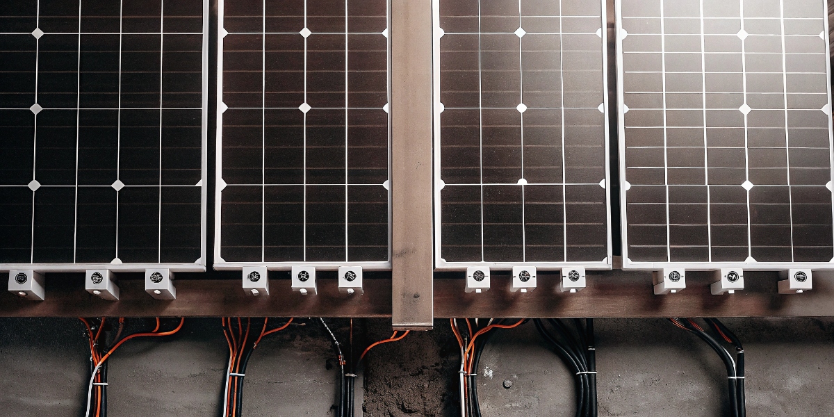
The way you wire your panels determines the voltage. If the voltage does not match the common DC bus requirement, the VFDs will not start.
You must connect panels in series strings to build up the voltage to the required DC bus level (usually 600V-800V for 400V motors). Then, you parallel these strings to increase the total current capacity to feed all three VFDs simultaneously.
Connecting wires is the easy part. The hard part is control. When you have one solar array powering three big loads, you have a supply and demand problem. What happens if the sun is weak, but all three motors try to run at 100% speed? The voltage will collapse. The whole system will trip.
To solve this, I use a microgrid controller7. This is a smart brain for your system. You should ask your engineering team to include this.
The microgrid controller needs irradiance forecasting8. This sounds complex, but it is simple logic:
- Measure: Sensors see how much sun is available.
- Forecast: The controller predicts if a cloud is coming in the next minute.
- Orchestrate: It tells the VFDs what to do.
Without this controller, the VFDs are blind. They just try to pull power. With the controller, you align motor demand to real-time PV output.
Here is how I structure the priority logic in the controller:
- Priority 1: Critical Pump. If sun is low, only this runs.
- Priority 2: Aux Fan. Runs only if excess power exists.
- Priority 3: Transfer Pump. Runs only at peak noon sun.
This reduces the need for expensive batteries. You do not need to store energy if you use it intelligently. You preserve torque and process continuity by managing the load side, not just the supply side. This saves a lot of budget on the battery bank.
Can we run two motors with one VFD?
Sometimes to save money, purchasing managers ask if we can just buy one big VFD and hook up two or three motors to it.
Yes, you can run two motors with one VFD if the VFD current rating is higher than the sum of both motors. However, for this solar architecture, I recommend individual VFDs for better control and stability.

While running two motors on one drive is possible, it is risky for solar applications. If you start two motors at once, the in-rush current is huge. This massive spike can pull down the solar voltage instantly.
Instead, using three smaller VFDs on a common bus is safer. But even then, starting a motor is hard on the system. Solar panels are "soft" sources. They cannot provide a sudden surge of power like the utility grid.
To fix this, I add a small DC-link buffer.
This can be:
- A bank of supercapacitors.
- A small, compact battery.
You connect this buffer directly to the common DC bus. It acts like a shock absorber.
When a motor starts, it needs a kick of energy. The supercapacitors9 provide this kick. The solar panels do not feel the shock. This prevents the voltage from dipping too low.
This small addition allows you to shrink your inverter sizing margins. You do not need to buy a VFD that is 2x the size just to handle the start-up. You can buy the correct size.
Also, this buffer helps with "cloud transients." If a small cloud covers the sun for 10 seconds, the buffer holds the voltage up. The motors keep spinning. Without the buffer, the system would stop and restart constantly. This protects your machinery from wear and tear. It creates higher uptime at a lower capital expenditure (capex).
Conclusion
To connect three VFDs to one solar system, use a common DC-bus architecture with fused isolation. Install a microgrid controller to manage loads based on sunlight, and add a DC buffer to handle start-up surges.
-
Understanding this architecture can help optimize your solar power system for efficiency and cost savings. ↩
-
Learn about MPPT technology to maximize energy harvest from solar panels. ↩
-
Discover how MPPT enhances solar energy efficiency and performance. ↩
-
Find out how active front ends improve system stability and efficiency. ↩
-
Learn how harmonic filters can protect your equipment and improve power quality. ↩
-
Understanding THD is crucial for maintaining the health of electrical systems. ↩
-
Discover how microgrid controllers optimize energy management in solar systems. ↩
-
Learn how forecasting can improve the efficiency of solar power systems. ↩
-
Explore the benefits of supercapacitors for energy storage and management. ↩
